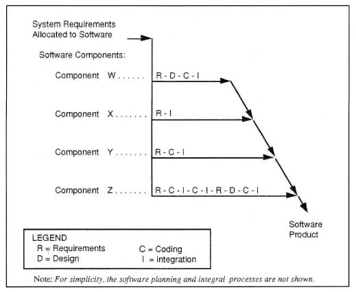
Software High Level Requirements
From the system requirements, we can help you define high level software requirements.
The high level software requirement definition, is the expression of the system requirements
specifically to be implemented in code. Each software requirement is systematically traced
to a system requirement. Justification is provided for any derived requirements.
Software requirements definitions are written by following best practices guidelines.
Software Low Level Requirements
The low level requirements are the expression of the code at the level the closest
to the programming language. Each software requirement is systematically traced to
a software high level requirement. Software requirements definitions are written by
following best practices guidelines. When an automated code generation tool is used
the picture is the low level requirement.
DO-178B
The following is a typical example of a fuel metering unit software requirements.
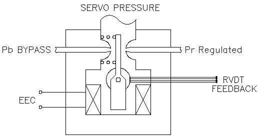
Software High Level Requirements | |||
| CL_0000001 | SRD 5.2.1:FCU RVDT | TYPE : DRV | SR : R123574 |
| The CL shall read the FCU RVDT Voltage Feedback [OSIN_FCU_RVDT_VFBK] in engineering unit (mV) from the Operating System. | |||
| CL_0000002 | SRD 5.2.1:FCU RVDT | TYPE : HLR | SR : R123574 |
| The CL shall input the FCU RVDT Voltage Feedback [OSIN_FCU_RVDT_VFBK] into a 2 dimensional map [MAP2D_FCU_RVDT_MV_TO_DEG] to determine the FCU Feedback Angular Position [FCU_RVDT_ANG] in degrees. | |||
| CL_0000003 | SRD 5.2.1:FCU RVDT | TYPE : HLR | SR : R123574 |
| The CL shall define the 2 dimensional curve (FCU RVDT Voltage Feedback to FCU RVDT Angular Position) [MAP2D_FCU_RVDT_MV_TO_DEG] as per a the following (x,y) points. | |||
| CL_0000004 | SRD 5.2.1:FCU RVDT | TYPE : DRV | SR : R123574 |
| The CL shall range limit the output of the 2 dimensional curve (FCU RVDT Voltage Feedback to FCU RVDT Angular Position) [MAP2D_FCU_RVDT_MV_TO_DEG] between the minimum y value and maximum y value defined in the map. | |||
| CL_0000005 | SRD 5.2.7:FCU CONTROL LOOP | TYPE : HLR | SR : R123572 |
| The CL shall calculate the FCU RVDT Position Error [FCU_RVDT_POS_ERR] as per the following equation. FCU Position Error = FCU Position Setpoint - FCU RVDT Angular Position | |||
| CL_0000005 | SRD 5.2.7:FCU CONTROL LOOP | TYPE : HLR | SR : R123572 |
| The CL shall calculate the FCU RVDT Position Error [FCU_RVDT_POS_ERR] as per the following equation. FCU Position Error = FCU Position Setpoint - FCU RVDT Angular Position | |||
| CL_0000006 | SRD 5.2.7:FCU CONTROL LOOP | TYPE : HLR | SR : R123572 |
| The CL shall input the FCU Position Error in a Dynamic Filter and output the FCU Torque Motor Current. | |||
| CL_0000007 | SRD 5.2.7:FCU CONTROL LOOP | TYPE : DRV | SR : R123572 |
| The CL shall use a PID Compensation for the FCU Dynamic Filter. | |||
| CL_0000008 | SRD 5.2.7:FCU CONTROL LOOP | TYPE : DRV | SR : R123572 |
| The CL shall reset the PID integral gain to 0.0, when the CL is cycled for the first time. | |||
| CL_0000010 | SRD 5.2.10:FCU FAULT DETECTION | TYPE : DRV | SR : R123579 |
| The CL shall input the FCU RVDT Position Feedback into a first order lag filter with a 200ms time constant. | |||
| CL_0000011 | SRD 5.2.10:FCU FAULT DETECTION | TYPE : HLR | SR : R123579 |
| The CL shall detect a FCU Position tracking error if the following condition is met : ABS(FCU Position Setpoint-Filtered FCU RVDT Position)>10 degrees | |||
| CL_0000012 | SRD 5.2.10:FCU FAULT DETECTION | TYPE : HLR | SR : R123579 |
| The CL shall latch a FCU Position Tracking Error Fault when the FCU Position Tracking Error is set for more than 2 sec. | |||
| CL_0000013 | SRD 5.2.10:FCU FAULT DETECTION | TYPE : HLR | SR : R123580 |
| The CL shall set the FCU Torque Motor Current to 0.0 when a FCU Position Tracking Error Fault is set. | |||
| CL_0000014 | SRD 5.2.10:FCU FAULT DETECTION | TYPE : DRV | SR : R123580 |
| The CL shall reset the FCU Integral Gain to 0.0 when a FCU Position Tracking Error Fault is set. | |||
| CL_0000015 | SRD 5.2.15:FCU OUTPUT | TYPE : DRV | SR : |
| The CL shall output the FCU RVDT Torque Motor Current [OSOUT_FCU_TQCUR] in engineering unit (mV) to the Operating System. | |||
Software Low Level Requirements | |||
| SL_0000001 | SDD 3.2.1:FCU RVDT | TYPE : LLR | CL : 0000001 |
| The FCU RVDT Voltage Feedback Current Value in engineering unit (mV) [OSIN_FCU_RVDT_VFBK.k] shall be read from the Operating System analog input array IN_OS_ANLG[0]. | |||
| SL_0000002 | SDD 3.2.1:FCU RVDT | TYPE : DRV | CL : 0000001 |
| The FCU RVDT Voltage Feedback Last Past Value in engineering unit (mV) [OSIN_FCU_RVDT_VFBK.k1] shall be equal to its Current Value. | |||
| SL_0000003 | SDD 3.2.1:FCU RVDT | TYPE : LLR | CL : 0000003 |
| The FCU RVDT Voltage to FCU Angular Position Map [MAP2D_FCU_RVDT_MV_TO_DEG] shall be defined by the following points : MAP2D_FCU_RVDT_MV_TO_DEG.x1=-14.6; MAP2D_FCU_RVDT_MV_TO_DEG.y1=12; MAP2D_FCU_RVDT_MV_TO_DEG.x2=187; MAP2D_FCU_RVDT_MV_TO_DEG.y2=-98; | |||
| SL_0000004 | SDD 3.2.1:FCU RVDT | TYPE : LLR | CL : 0000002 |
| The FCU RVDT Angular Position in Degree [FCU_RVDT_ANG] shall be calculated using the 2D linear interpolation function linint2dim2ptsfunc that uses the FCU RVDT Position vs Voltage Feedback Map [MAP2D_FCU_RVDT_MV_TO_DEG] for its map input (1st input), and uses the FCU Angular Position [OSIN_FCU_RVDT_VFBK] for its parameter input (2nd input). | |||
| SL_0000005 | SDD 3.2.1:FCU RVDT | TYPE : LLR | CL : 0000004 |
| The FCU RVDT Angular Position low and high values [RNGLIM_FCU_RVDT_ANG] shall be defined as the minimum and maximum value of thein the for The FCU RVDT Voltage to FCU Angular Position Map [MAP2D_FCU_RVDT_MV_TO_DEG]. | |||
| SL_0000006 | SDD 3.2.1:FCU RVDT | TYPE : LLR | CL : 0000004 |
| The FCU RVDT Angular Position Range Limited [FCU_RVDT_ANG_RNGLIM] shall be calculated using the range limiting function rnglimfunc that uses that uses the FCU RVDT Angular Position low and high values defined in [RNGLIM_FCU_RVDT_ANG] for its range input (1st input), and uses the FCU RVDT Angular Position [FCU_RVDT_ANG_RNGLIM] as its parameter input (2nd input). | |||
| SL_0000007 | SDD 3.2.1:FCU RVDT | TYPE : LLR | CL : 0000005 |
| The FCU RVDT Position Error [FCU_RVDT_POS_ERR] shall be calculated by substracting the FCU Position Setpoint [FCU_RVDT_SET_POINT] from the FCU RVDT Angular Position [FCU_RVDT_ANG_RGLM]. | |||